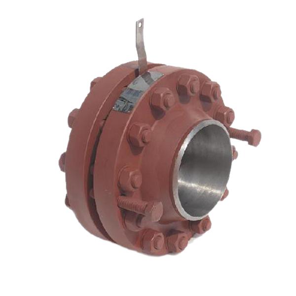
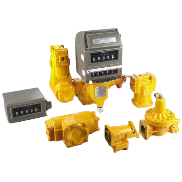
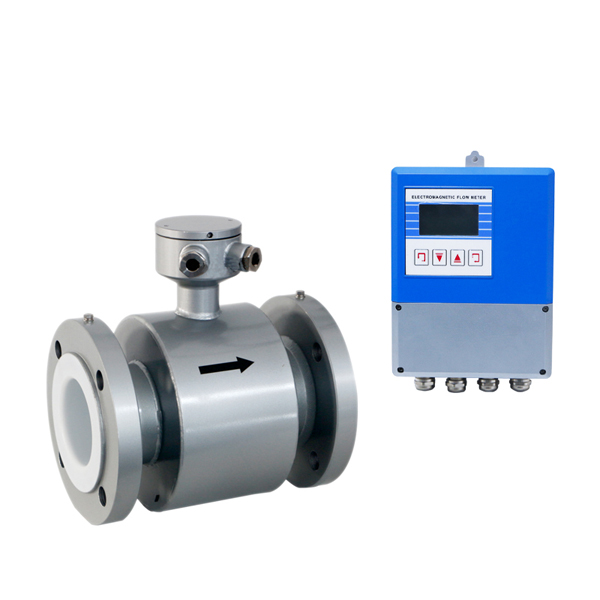
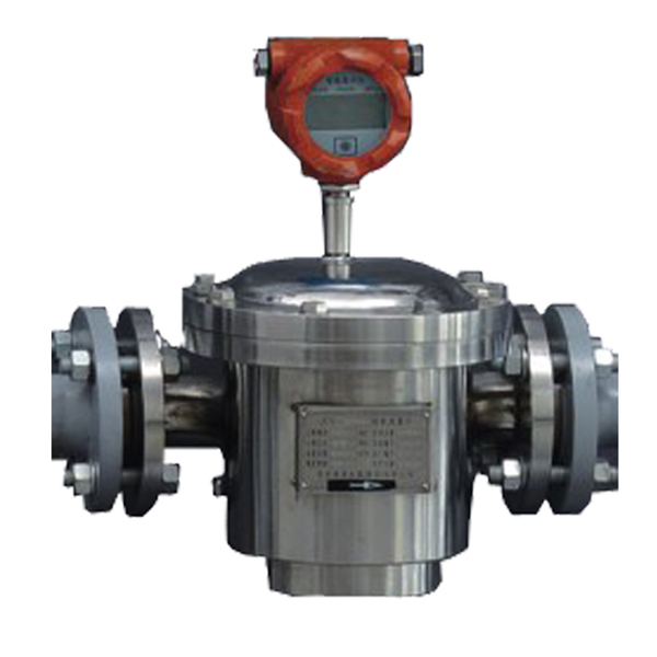
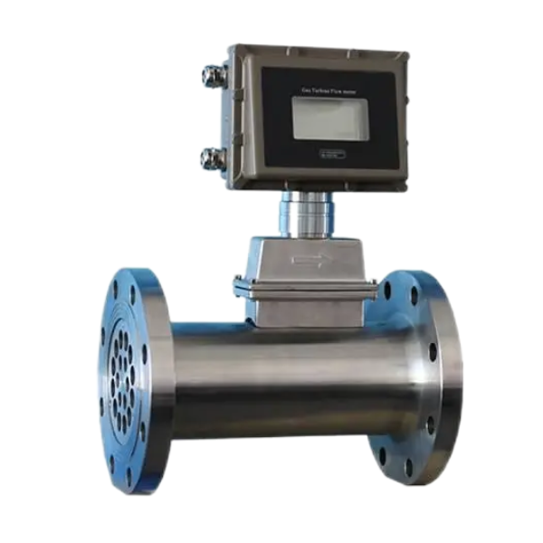
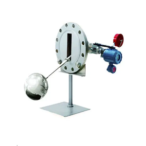
Orifice Flow Meter

- Dedan
- China
- 30 days
- 50 sets/month
Throttle device is the most historic and most extensively used flow measurement instrument. Its features are simple structure, easy installation, stable performance and high accuracy, etc.
Orifice flow meter
Throttle device is the most historic and most extensively used flow measurement instrument. Its features are simple structure, easy installation, stable performance and high accuracy, etc merits. It can be used for flow measurement for liquid, steam and gas in modern industries.
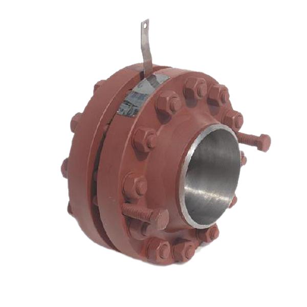
Summary Orifice Flow Meter
Throttling orifice is suitable for automatic control, piping and other professional situations in the engineering design, here are several occasions which are frequently used :
a. It required that fluid with small flow continuously passing it, such as analysis on the sampling pipeline, pump flush pipeline, hot standby pump bypass line and so on, can set the current limit orifice to implement;
b. It required fluid step-down occasions, such as setting limit flow orifice after the control valve to minimize the pressure drop on the valve, reduce the noise of the valve, reduce the wear of valve seat and valve element, avoid liquid flash vaporization and cavitation phenomenon behind the valve, prolong the service life of the valve; Fluid requires step-down, you can use the current limit orifice plate to step-down for the application that step-down precision is not high;
c. Application required fluid step-down and current limiting, such as setting the current limit orifice plate on bypass control valve, in order to prevent the operation of the bypass, liquid pressure drops too fast or causes danger such as liquid evacuated. For piping emptying system, when big pressure drops and produces a lot of noise, you can use current-limiting orifice plate to reduce the noise, to improve the production environment.
Model Selection Table
L G X L — □ □ □
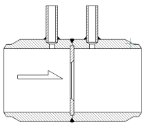
figure 1 Nominal diameter code and meaning
01 | 016 | 02 | 026 | 03 | 04 | 05 | 06 | 08 | 10 | |||
DN | mm | 10 | 15 | 20 | 25 | 32 | 40 | 50 | 65 | 80 | 100 | |
in | 1/2 | 3/4 | 1 | 1-1/4 | 1-1/2 | 2 | 2-1/2 | 3 | 4 | |||
Code | 12 | 15 | 20 | 25 | 30 | 35 | 40 | 45 | 50 | 60 | ||
DN | mm | 125 | 150 | 200 | 250 | 300 | 350 | 400 | 450 | 500 | 600 | |
in | 5 | 6 | 8 | 10 | 12 | 14 | 16 | 18 | 20 | 24 | ||
Code | 70 | 80 | 90 | 91 | 92 | 93 | ||||||
DN | mm | 700 | 800 | 900 | 1000 | 1100 | 1200 | |||||
in | 28 | 32 | 36 | 40 | 44 | 48 | ||||||
· LGXL Throttling Orifice
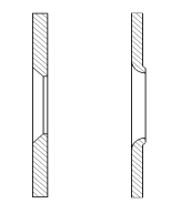
Figure 2 Nominal pressure code and meaning
01 | 02 | 03 | 04 | 05 | 06 | 10 | 11 | 15 | 16 | ||
PN | MPa | 1.6 | 2.0 | 2.5 | 4.0 | 5.0 | 6.3 | 10.0 | 11.0 | 15.0 | 16.0 |
Class | 150 | 300 | 600 | 900 | |||||||
Code | 25 | 26 | 42 | ||||||||
PN | MPa | 25.0 | 26.0 | 42.0 | |||||||
Class | 1500 | 2500 | |||||||||
Figure 3 Straight pipe code and meaning

