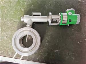
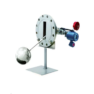
Metal Tube Variable Area Float Flow Meter

- Dedan
- China
- 30 days
- 50 sets/month
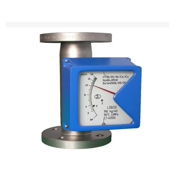
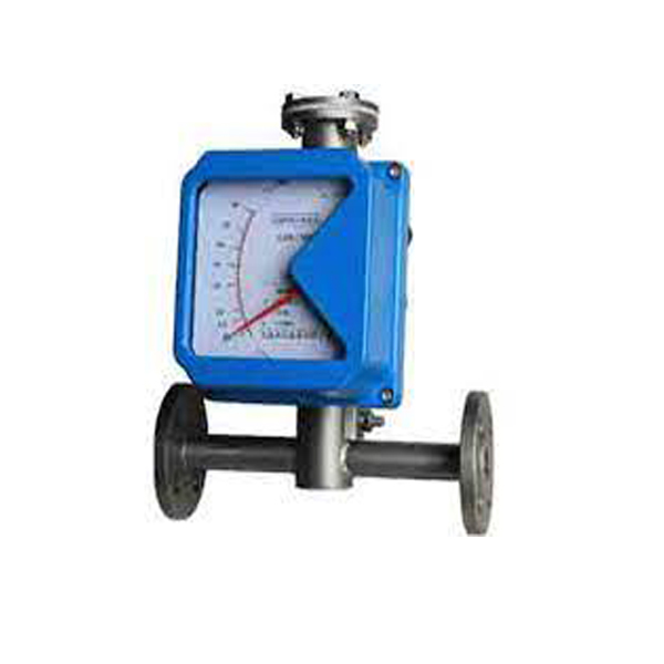
The variable Area Flow meter is an instrument for measuring the flow of liquids or gases in pipelines. It includes a vertical tube through which the fluid flows whose diameter increases from the bottom to the top and a float.
Metal Tube Variable Area Float Flow Meter
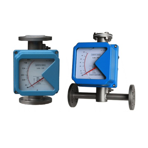
DESCRIPTION Metal Tube Variable Area Float Flow Meter
The variable Area Flow meter is an instrument for measuring the flow of liquids or gases in pipelines. It includes a vertical tube through which the fluid flows whose diameter increases from the bottom to the top and a float which can move vertically in the tube. As the flow increases this float moves to a higher position until its resistance to the fluid flow is balanced by th?float's buoyed weight in the fluid, a value which is constant and independent of the flow rate. The position of the iloat is a measure of the flow rale. The flow rate values can be read on a scale.
TECHNICAL DATA Metal Tube Variable Area Float Flow Meter
Application Range | (1)Gas;(2)Liquid;(3)Steam |
Turndown Ratio | 10:1 |
Accuracy(Refer to the accuracy on the nameplate) | ±1.0% & ±1.5% &± 2.5% |
Temperature | |
Max. Process Temperature | T1 level:150℃ |
T2 level:300℃ | |
T3 level:350℃ | |
Pressure | |
Nominal Operating Pressure | DN15{aspcms:sitetitle}.DN50:4.0Mpa |
DN65{aspcms:sitetitle}.DN200:1.6Mpa | |
Max. Pressure Rating | DN15:32Mpa; DN25:25Mpa;DN50:20Mpa |
DN80:10Mpa;DN100:6.4Mpa | |
DN125{aspcms:sitetitle}.DN150:4.0Mpa | |
MODEL SELECTION Metal Tube Variable Area Float Flow Meter
Model | SH250 | Description | |||||||||
Diameter | XXX | 015: DN15 100: DN100 200: DN200 | |||||||||
Power Supply | N | Mechanical Display; No output | |||||||||
A1 | Mechanical Display; 0-1000Hz Output | ||||||||||
A2 | Mechanical Display; 4-20mA Output; 24V DC | ||||||||||
B | LCD Display; No Output; Battery | ||||||||||
C | LCD Display; Pulse Output; 24V DC | ||||||||||
D | LCD Display; 4-20mA + Pulse Output; 24V DC power supply | ||||||||||
Notice | RS485 and Hart are optional for C and D converter | ||||||||||
Reset Function | Y | Yes | |||||||||
N | No | ||||||||||
Flow Range | XX | Refer to the Range Table | |||||||||
Fluid | L | Liquid | |||||||||
G | Gas | ||||||||||
Material | S4 | Body and Float: SS304 | |||||||||
S6 | Body and Float: SS316 | ||||||||||
SF | Body: SS304; Float: PTFE | ||||||||||
XX | On request | ||||||||||
Installation Way | H | Horizontal Installation | |||||||||
V | Vertical Installation | ||||||||||
Structure | 1 | Standard Structure | |||||||||
2 | Heat Insulation | ||||||||||
3 | Damper for gas measurement | ||||||||||
4 | High Temperature | ||||||||||
5 | High Pressure | ||||||||||
Explosion Proof | NA | Safety Field without Ex-Proof | |||||||||
BT | Exd II BT4 | ||||||||||
CT | Exib II CT4 | ||||||||||
Connection | DXX | D16: DIN PN16 flange; D25: DIN PN25 … | |||||||||
AXX | A15: ANSI 150# flange; A30: ANSI 300#… | ||||||||||
JXX | J10: JIS 10K flange; J20: JIS 20K … | ||||||||||

