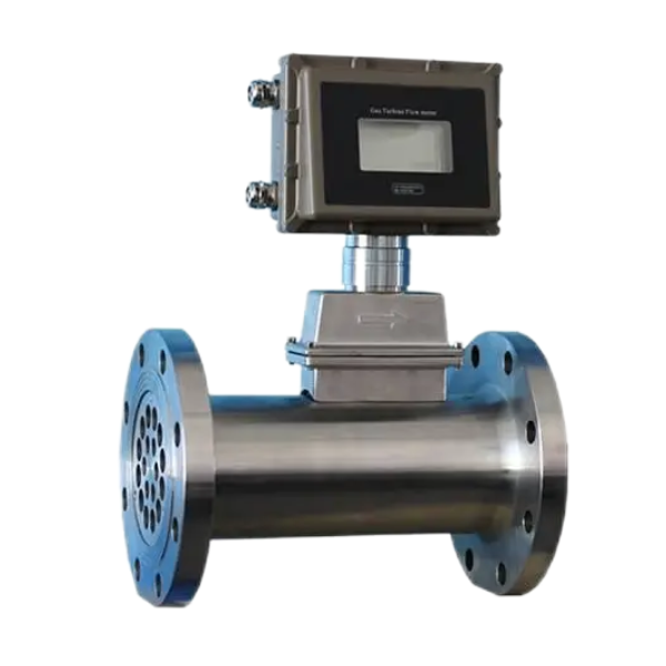
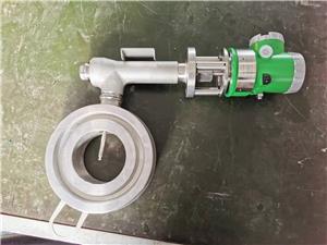
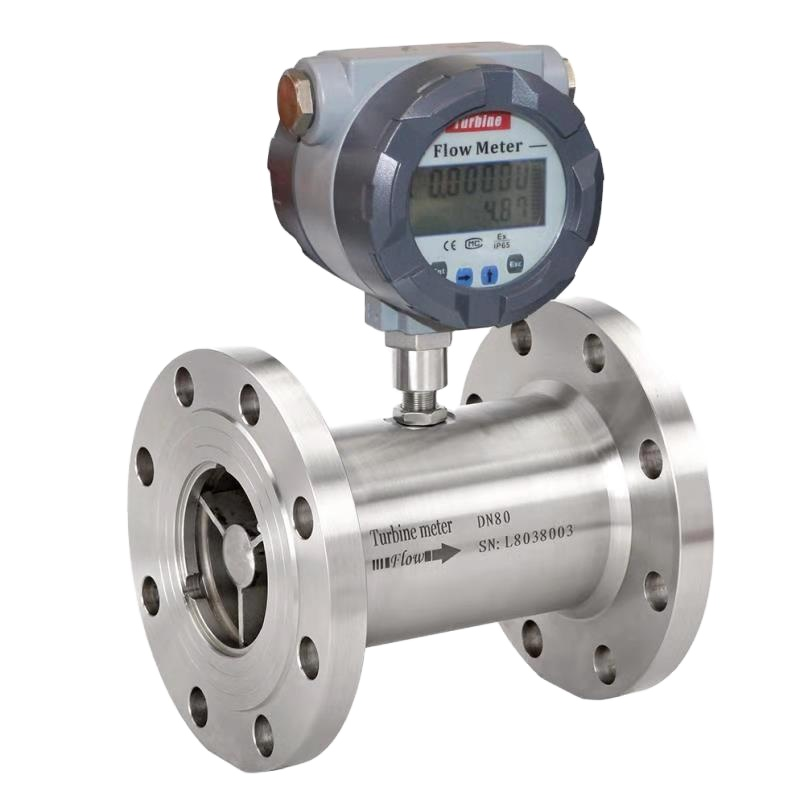
Diesel Liquid Turbine Flow Meter

- Dedan
- China
- 30 days
- 50 sets/month
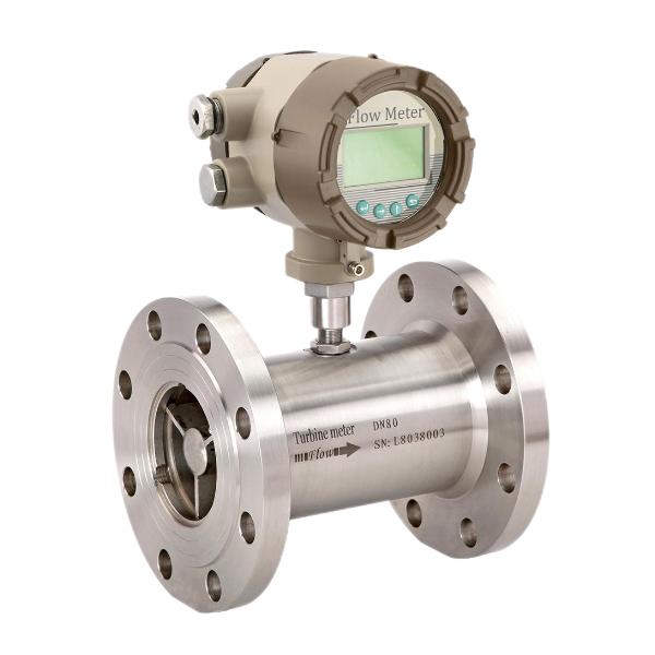
The liquid turbine flow meter in the series LWGY are specially designed for usage in water, diesel, gasoline and other fluid measurement and control systems. They operate according to the turbine principle.
Diesel Liquid Turbine Flow Meter
OPERATING PRINCIPLE Diesel Liquid Turbine Flow Meter
Fluid entering the meter first passes through an inlet flow straightener that reduces its turbulent flow pattern. Fluid then passes through the turbine, causing the turbine to rotate at a speed proportional to fluid velocity. As each turbine blade passes through the magnetic field generated by the meter's magnetic pickup, an AC voltage pulse is generated. These pulses provide an output frequency that is proportional to volumetric flow.
DESCRIPTION Diesel Liquid Turbine Flow Meter
The liquid turbine flow meter in the series LWGY are specially designed for usage in water, diesel, gasoline and other fluid measurement and control systems. They operate according to the turbine principle, i.e. the speed of an impeller turning in the fluid flow is measured and converted into pulse or 4-20mA signals
Technical Data Diesel Liquid Turbine Flow Meter
-Output: Pulse; 4-20mA
-Accuracy:±1.0 of Rate;±0.5% of Rate
-Operating Temp.: -2O..,+6O℃
-Fluid Temp.: -2O...+ 15O℃
-Body Material: SS304; SS316
-Rotor Material: 2Cr13;CD4MCu
-Bearing Material: Tungsten Carbide
MODEL SELECTION Diesel Liquid Turbine Flow Meter
Model | Suffix Code | Description | ||||||||
Diameter | XXX | Stand tor diameter 004: DN4: 006: DN6 DN4-DN200 | ||||||||
Converter Type | N1 | 24V DC; Pulse output; No display | ||||||||
N2 | 24V DC; Pulse output;No display; Ex | |||||||||
A | 24V DC; 4-20 mA output; Nodisplay; Ex | |||||||||
E1 | Battery power supply; No output; Ex; Digital Display | |||||||||
E2 | 24V DC; 2-wire 4-20mA output;Ex; Digital Display | |||||||||
E3 | 24V DC; Pulse output; Ex;Display | |||||||||
E4 | 24V DC; 0-20mA output; EX; Digital display | |||||||||
E5 | 24V DC; 3-wire 4-20mA / Pulse output; EX; Digital display | |||||||||
M | 220Vac; 4-20mA output; EX; Digital display | |||||||||
FE | FE:Fluidwell E series converter | |||||||||
FF | FF:Fluidwell F series converter | |||||||||
Notice: | 1)Modbus RS485 is optional for E2,E3,E4,E5 and M type | |||||||||
2)Dual Power(24VDC+Battery) is optional for E2,E3,E4,E5,G | ||||||||||
Accuracy | 10 | ±1.0% of Rate | ||||||||
05 | ±0.5% of Rate | |||||||||
Flow Range | S | Standard Range | ||||||||
E | Extended Range | |||||||||
Body Material | S4 | SS304 | ||||||||
S6 | SS316 | |||||||||
PL | Plastic (DN15-DN50) | |||||||||
Rotor Material | Cr | 2Cr13 | ||||||||
CD | CD4MCu | |||||||||
Explosion Proof | BT | Exd II BT6 | ||||||||
NA | No explosion proof | |||||||||
Connection | THM | Male thread; Available from DN4 … DN50 | ||||||||
THF | Female thread; Available from DN4 … DN50 | |||||||||
WAF | Wafer connection | |||||||||
DXX | D16: DIN PN16 flange;D25: DIN PN25… | |||||||||
AXX | A15: ANSI 150# flange;A30: ANSI 300#... | |||||||||
JXX | J10: JIS 10K flange;J20: JIS 20K… | |||||||||
Temperature | T1 | -20...+80 °C | ||||||||
T2 | -20...+120 °C | |||||||||
T3 | -20...+150 °C | |||||||||

