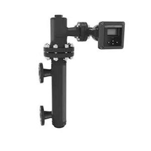
foxboro 244LD UTZ model displacer level transmitter from Dandong
orking principle
The change in the liquid level of the measured medium causes a change in the buoyancy of the inner cylinder, which is transmitted to the torque tube assembly to rotate the torque tube at an angle simultaneously. A sensing system coupled to the torque tube mandrel generates a voltage signal. The level controller electronic component measures the fluid (boundary) signal to provide 4 ~ 20 mA current output. The ambient temperature measured by the microcontroller can compensate for the changes in the liquid density due to the process temperature changes. LCD can display information about analog output, process variables and percentage range of liquid (boundary) bits.
2.3 Packaging
Please send the packaging waste to a specialized recycling facility.
2.4 During hoisting and transportation
Please select qualified lifting equipment and lifting belt, and pay attention to safety.
2.5 Warehousing
Storage temperature is-20℃ ~40℃; storage humidity is 40%.
3 Technical features
3.1 Main performance
3.1.1 It has passed the national explosion-proof certification
Certification mark: safety type Ex ia ⅡCT4 ~ T 6 Ga
Burtal type Ex db ⅡCT4 to T 6 Gb
3.1.2 Product implementation standards
GB / T13969 float type liquid level instrument.
3.2 Main parameters
3.2.1 Power supply voltage: 12~30V DC.
3.2.2 Output signal: 4 ~ 20 m ADC.
4 Schemram of external dimensions
If a special size is required in order, the actual size shall prevail.

5 Open the box and check
5.1 Notes for unpacking and inspection
5.1.1 Whether the reference product nameplate is consistent with the supply list information.
5.1.2 Check the quantity of each part and the correct material according to the packing list.
5.2 Check the content
5.2.1 Check the instrument appearance for defects, damage and other abnormal conditions.
5.2.2 If the UTZ intelligent buoy transmitter and other parts use separate packaging.
6 Installation
6.1 Install the tools
6.1.1 Wrench, flange spacers and flange bolts for process connections
6.1.2 Level
6.2 Installation technical requirements
6.2.1 When installing the measuring room, the flange axis of the outer cylinder side must be perpendicular to the horizontal plane (calibrated with the horizontal meter). If the UTZ intelligent buoy transmitter and other parts are packed separately, it shall be installed according to the positions shown in the product structure diagram; if the whole part has been installed, operate according to 6.3.5.
6.2.2 Installation of the transmitter and the inner tube: hold the hanging plate on the inner tube by hand and hang it on the top of the transmitter lever.