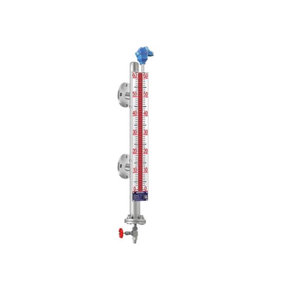
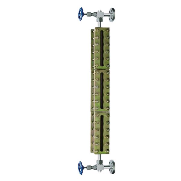
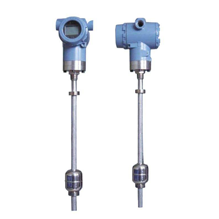
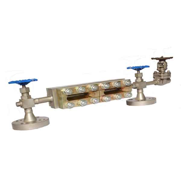
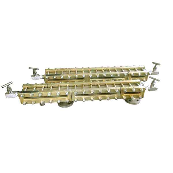
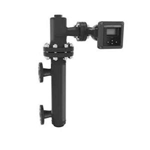
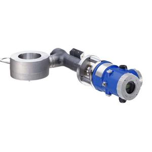
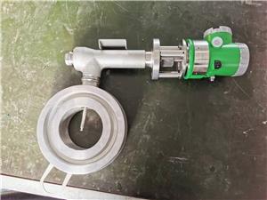
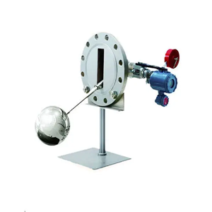
Magnetic Side To Side Float Level Indicator

- Dedan
- China
- 30 days
- 500 sets/month
UHC series magnetic float level transmitter and UQC series magnetic ball float level transmitter are new designed generation level indicator according to magnetic coupling principle.
Magnetic Side To Side Float Level Indicator
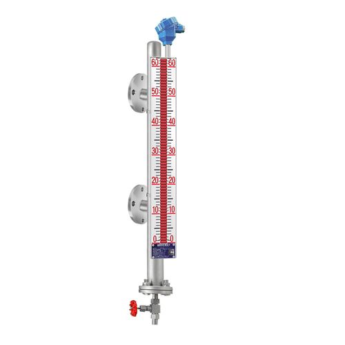
>>Technical parameters
◇ Local indication part:
Measuring range: 500~15000mm
Indication error: ± 10 mm
Connecting flange: DN20 (top mounted DN150)
Working temperature: - 196~450 ℃
Density difference: 0.25g/cm3
Medium viscosity: ≤ 0.15Pa • s
Tracing pressure: 0.6 MPa
Heat tracing joint: G1/2“
Flange standard: JB/T82.1-94, JB/T82.2-94 or manufactured according to the flange standard provided by the user
◇ Remote transmission part:
Measuring range: 500~12000 mm
Accuracy class: ± 10 mm
Power supply voltage: 24V DC
Output signal: 4~20mADC
Load resistance: max. 950
Electrical interface: M20 × 1.5
Explosion-proof sign: intrinsically safe type: Exia Ⅱ CT4/T5/T6Ga;
Explosion-proof type: Exd Ⅱ CT6 Gb
◇ Alarm part:
Output signal: switch signal
Alarm error: ± 5 mm
Contact capacity: 220V 5A
Alarm interface: M20 × 1.5
Model selection of magnetic float level indicator
Model | Code | Code meaning | ||||||||||||||||
UHC- | Magnetic float level transmitter | |||||||||||||||||
UHC.GY- | High pressure magnetic float level transmitter | |||||||||||||||||
UHC.GW- | High temperature magnetic float level transmitter | |||||||||||||||||
UHC.F- | Antirot magnetic float level transmitter | |||||||||||||||||
UHC.O- | Vacuum jacket magnetic float level transmitter | |||||||||||||||||
UQC- | Magnetic ball float level transmitter | |||||||||||||||||
M | With local indicator | |||||||||||||||||
N | Without local indicator | |||||||||||||||||
S | ||||||||||||||||||
U | With magnetostrictive remote level transmitter | |||||||||||||||||
T | Without remote level transmitter | |||||||||||||||||
A | With upper or lower limit alarm | |||||||||||||||||
C | With upper and lower limit alarms | |||||||||||||||||
D | Without alarm | |||||||||||||||||
E | PN1.0MPa | |||||||||||||||||
F | PN1.6MPa | |||||||||||||||||
G | PN2.5MPa | |||||||||||||||||
J | PN4.0MPa | |||||||||||||||||
H | PN6.3MPa | |||||||||||||||||
O | PN10MPa | |||||||||||||||||
P | PN16MPa | |||||||||||||||||
Q | Other pressure class | |||||||||||||||||
* | Level ρ or interface ρ1 /ρ2 | |||||||||||||||||
- | ||||||||||||||||||
* | Measuring range. For UQC, please note the neck length. | |||||||||||||||||
d | Explosion isolation | |||||||||||||||||
i | Intrinsically safe | |||||||||||||||||
Additional code | W | With steam jacket (ZG1/2” male thread) | ||||||||||||||||
L1 | Vent valve above | |||||||||||||||||
L2 | Blow-down valve below | |||||||||||||||||
L3 | Vent valve above and blow-down valve below | |||||||||||||||||
□- | □ | □ | □ | □ | □ | - | □ | □ | □ | □ | ||||||||
Order requirements of magnetic float level indicator
Please select product model according to the model selection table.
◆ Medium name and density
◆ Medium operating pressure & temperature
◆ Wetted material
◆ Range
◆ Flange standard

